Title
Atlas configuration and maintenance display and control panelCatalog Number
102733058Type
Physical objectDescription
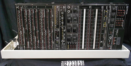
This object consists of a base enclosure and a panel enclosure. The base enclosure is a nondescript metal enclosure; the panel enclosure is black enclosure and extends 1.25" out from the base. It is hinged along one side to swing out from the base; the other side has screwdriver-operated latches to secure the panel; a catch locks the panel when swung out. There is an annunciator/button panel on the back of the base, it is 2.25" high and 16" wide. Mounted thereon are a '1' cut out of the aluminum of the panel; 7 rectangular button/indicators; and a metal plate on which is printed CENTRAL PROCESSOR.The front panel is divided into 11 main sections; each section consists of an assortment of switches, LEDs, pushbuttons, and BNC connectors. The printing on the panel is white against the black background. The top two sections are labeled CONFIGURATION and the remaining sections are labeled MAINTENANCE DISPLAY & CONTROL. The CONFIGURATION section has 7 subsections. Left to right and top to bottom there are a group of 4 rows of 6 red toggle switches; to the right a row of 7 red toggle switches (with room for 11 more); below those a section containing four 4-position rotary switches; a section with 2 red toggle switches; and three sections with one control: a protected pushbutton; a red toggle switch; and a red toggle switch. The first section in the MAINTENANCE DISPLAY & CONTROL has a single row of 35 toggle switches with white or black handles; below that there are two subsections, the left having 17 toggle switches (black or white handles), and to the right a section containing a red LED, a LAMP TEST button, and a protected INITIALIZE button.
Thumb wheels that scroll 14 legends for associated red indicators makeup next 2 sections. Each scroll has a row of 35 LED indicators above it and 35 below; the top row is numbered 0 to 35 and the bottom row numbered 36 to 71.
The next 2 sections together have 9 subsections; 7 of these have rotary switches ranging between 8 and 13 positions; a subsection with a red LED indicator and 2 protected buttons; and a section with 3 rows of 4 red LEDs and a row of yellow toggle switches. The next section has 2 subsections: the first with a black pushbutton, a BNC connector, and 3 yellow toggle switches; and the other with 7 yellow toggle switches, a protected button, a pushbutton, and a 5-position rotary switch. The next section has 3 subsections: a row of 17 yellow toggle switches; 5 red LED indicators and a pushbutton; and a yellow toggle switch, a 6-position rotary switch, and a pushbutton.
The lowest and largest section has 10 rows of between 32 and 37 red LEDs. The lower left corner has a BNC connector, and the lower right corner has a 4-position rotary switch.
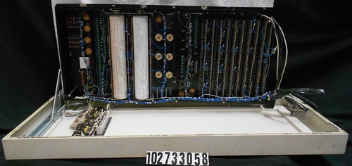
The back side of the panel consists of wire-wrap. Blue 30-gauge wire is used for most connections; some other colors, twisted 30-gauge wires, and larger wires are used for the rest. The toggle switches have wire-wrap contacts. The wafer rotary switches, the protected buttons, pushbuttons, and binding posts for resistors have solder terminals to which the 30-gauge wires are soldered. The rows of LEDs are mounted on circuit boards with their drivers and have wire-wrap pins. All external-going conductors are wire-tied and lead toward the hinge side of the panel, bound in place by adhesive mounts. The wires then go to the bottom of the panel and are split among 3 black sleeves. Power and ground is supplied by bus strips along the latch side of the panel.
Near the top of the back enclosure there is a black cross member supporting 2 PCBs, the 7 button/indicators, and a terminal strip with 24 double screw connections. White wire interconnects local components; black-and-white twisted pairs provide external connections.
Discoloration on the lip of the back enclosure indicates that there was a cover to close the gap between itself and the panel enclosure, but the cover is missing.
Identifying Numbers
| Other number | 210 | Stamped in black ink along the long edge opposite the one described above of a PCB mounted to a black cross member mounted inside the base enclosure. |
| Other number | 43C233501G | Printed in white ink on a PCB mounted above a black cross member mounted inside the base enclosure. |
| Other number | 43D232296G2 REVW | Printed in white felt tip pen on the upper left corner inside the panel enclosure. |
| Other number | 43D233549P1A | Etched in solder on a PCB mounted above a black cross member mounted inside the base enclosure. |
| Other number | 48040491-004REVB | Stamped in black ink on the upper left inside the base enclosure. |
| Other number | 54040142-001A | Printed in white ink along the short edge of a PCB mounted to a black cross member mounted inside the base enclosure. |
| Other number | 54040144-001A | Etched in solder along the long edge of a PCB mounted to a black cross member mounted inside the base enclosure. |
| Other number | 58016056-002 REVD | Printed in white felt tip pen on the upper left corner inside the panel enclosure. |
| Other number | A41 | Stamped in black ink on a PCB mounted above a black cross member mounted inside the base enclosure. |
Dimensions
base: 4 1/4 in; overall: 54 3/4 in x 23 5/8 in x 6 3/8 in; panel: 44 3/4 in x 20 1/4 in x 3 3/4 inCategory
I/O/console / panel