Title
Whirlwind vacuum tube module rackCatalog Number
102733206Type
Physical objectDescription
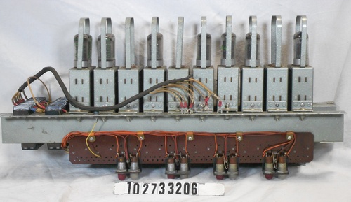
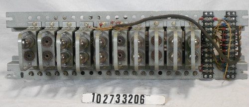
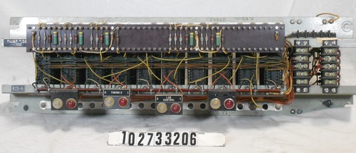
The rack is built around two identical frame members consisting of a piece of heavy metal that is bent up along one side and down along the other, resulting in an 'N'-shaped channel with a 1.75" bend up, a 2.25" horizontal surface, and a 0.625" bend down. Two of these, oriented in opposite directions, are held together with ten 24-contact edge connectors into which two-tube modules are inserted. Two 11-position screw terminal strips also span the two channels on the right side of the front. Twenty round holes to accommodate BNC connectors are drilled along the front of both channels; however, not all the holes are populated. On the back of the rack, phenolic boards with several rows of solder terminals are mounted to the horizontal sections of each channel, and another phenolic board with two rows of solder terminals is mounted perpendicular to the bottom one. Two 5-position screw terminal strips are mounted on the left side of the back of the rack, and one 4-position screw terminal strip is mounted to the bottom of the left end of the bottom channel.About 7 long bus wires are connected to pins of the module sockets to supply common signals and voltages. The two horizontal boards are also wired with two busses each. The vertical board attached to the bottom horizontal board hold the passive components of the rack. Wiring is point-to-point between the solder posts of the boards and the terminals of the module sockets. Some of the wiring terminates at the screw terminal strips. All but one of the external wires connected to the screw terminal strips are dressed with fabric cable wrap.
Four brackets that hold two neon lamp sockets each are mounted to the upper phenolic board. Each pair of sockets has a red lens and a clear lens. The inner two brackets are labeled with "LSR CONTROL" and "TIMING 2" with the white lamp lens labeled "0" and the red one labeled "1." The outer two brackets had labels but they are missing.
There is only one BNC connector in 20 holes along the top of the rack; nothing is attached to it. Sixteen of the holes along the bottom of the rack are populated with BNC connectors, and they also have nothing attached.
All module locations are occupied by 2-tube plug-in modules. The module model and serial numbers are, from left to right: GT BA# 358; FF# 341; GT BA# 150; FF# 302; GT BA# 688; FF# 439; GT BA# 692; FF# 362; GT BA# 1383; and GT BA# 198.
Date
1951Identifying Numbers
| Other number | 00649 | Stamped in blue ink on a paper sticker attached near the 4-screw terminal strip on the bottom of the lower left channel. |
| Other number | K15-A | Engraved white on black on a plastic label attached upside down to the right end of the upper channel. |
| Other number | PIUMP #136 | Engraved white on black on a plastic label attached upside down to the right end of the lower channel; a black unprinted Dymo label covers part of this number. |
| Serial number | 136 | Stamped in white ink on the left end of the upper channel of the rack. |
Dimensions
overall: 7 3/8 in x 26 in x 12 1/2 inCategory
Component/moduleCredit
Gift of Compaq Computer CorporationLot Number
X7422.2015